Vid Det Cam
Vid Det Cam
Vid Det Cam and products information
Vid Det Cam Function
Vid Det Cam integrates both camera and detector in a compact, stylish housing and detects vehicles waiting at or approaching an intersection. Vid Det Cam based on field-proven video detection technology - is part of the Tra fiction product range. Vid Det Cam is worldwide recognized as the market leader in traffic video detection.
About the products
This user guide describes the installation and setup of a VidDetCam system with 4Cam as the interface between VidDetCam, the PI, and the traffic controller. In addition, you can consult: 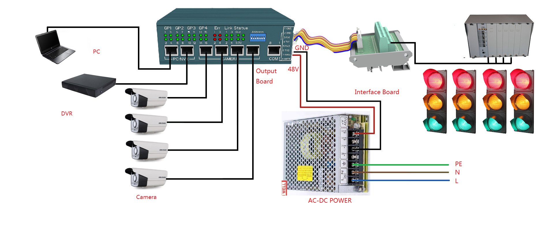
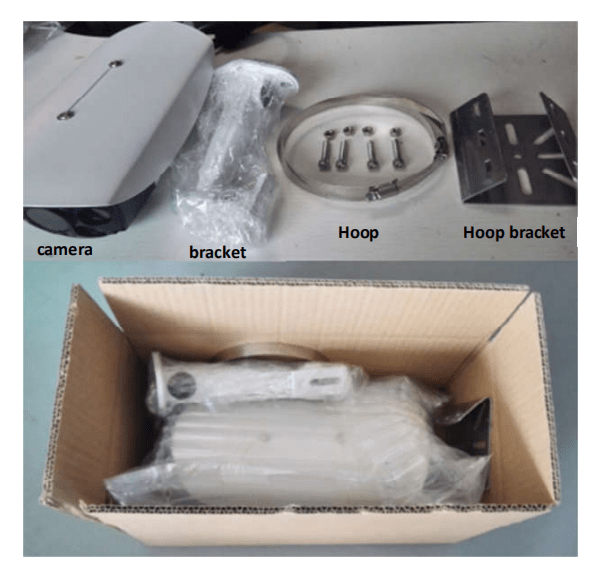
Contents of the VidDetCam package
The standard package includes VidDetCam, the connectors, and the mounting accessories. You will also find the quick reference card and power supply in this package.
Vid Det Cam LED indicator code
Output Board Introduction
Interface and Instructions:
1.Camera Detection Output Indication.
GP1 for camera ID 1 output signal group,ID2-ID16 is the same as this.
2.Camera Error Indicator。
When the system is power on, the indicator is always on.when the camera normal working, then the indicator will turn off.
3.Camera Connection Indicator
This indicator is always on when the camera is turned on normally.
4.Output Board Status Indication
3.3V The output board 3.3V Power working normally.
5.Output Board address setting5
When used more than 4 cameras for one intersection, we need setting addresses for the camera. see the table:
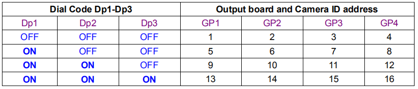
Dial code Dp4~Dp7are reserved.
6.PC/NVR interface
This interface is used to connect to a PC or NVR, a Non-POE network port.
NVR Requirements are compatible with H265 or H265+ network video recorders that support ONIF
protocol,also can buy it from our sales department.
7.CAMERA interface
Camera network port are POE port(Need insert POE fuse) or used as normal network port(remove
the POEfuse,Does not connect this port to a normal network device(if insert fuse), otherwise the device
maybe damaged, the 4 port is parallel.
Note:before plug the camera cable, the power must turn off. If not the Camera or Output board may
be damaged.
8.Universal Serial Port and RS485 Interface
| PIN | Definition |
| 1 | RS232 GND |
| 2 | RS232 GND |
| 3 | First RS232 RX |
| 4 | First RS232 TX |
| 5 | Second RS232 RX |
| 6 | Second RS232 TX |
| 7 | RS485 A |
| 8 | RS485 B |
When using the serial port or RS485 interface, please pay attention to the crystal head position 1-8 according to the standard pin position, please contact your local dealer for the communication protocol.
9.IO Interface Board Connector
When using the IO method to connect the traffic signal, please use the original cable to connect the output board to the interface board, and make sure the cable is connected reliably.
10.POE FUSE
The fuse is used to adjust the POE power output of the output board. If the camera is directly connected to the output board, the fuse must be connected, otherwise, the camera has no 48V power input. Some user Vid Det Cam is powered by an external POE. In this case, please unplug the fuse. Otherwise, the output board and external power supply and camera may be damaged. If you have any questions, please contact us.
11.Power Terminal
This terminal is the input power input end of the output board. Please follow the marked wiring. It is strictly prohibited to reverse the connection. Otherwise, the camera and output board will be burned out. The power input range is 24V ~ 42V DC, and the input power is 100W (power consumption when connecting 4 cameras). It is recommended to use the Mingwei power supply LRS-100-48.
Share this Post: